
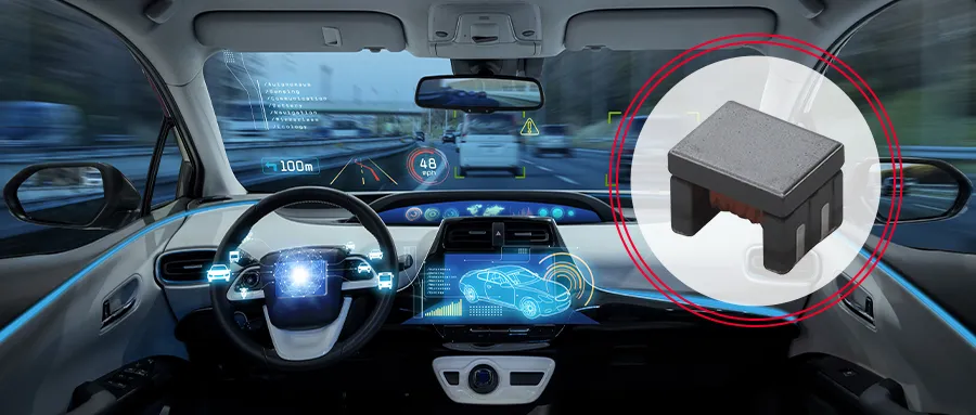
01 Popularization of Ethernet in Automotive Vehicles
02 Signal transmission through onboard Ethernet
03 Noise issues with in car Ethernet
04 Factors contributing to common mode noise
Noise reduction measures for 05 in car Ethernet
06 Notes on CMCC for in car Ethernet
07 Conducted emission countermeasures
08 DPI Test Countermeasures
Key points of DPI test countermeasures for 09
10 Summary
01
The Popularization of Ethernet in Automotive Vehicles
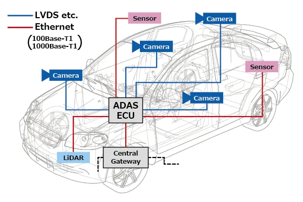
As devices that support ADAS, various sensors and cameras have gradually been configured in cars. Camera data transmission usually uses interfaces such as LVDS, while the use of in car Ethernet is gradually increasing when transmitting data from sensors such as LiDAR.
The office Ethernet adopts the 100Base-TX or 1000Base-T standards, while the Ethernet used for cars is specified to use the 100Base-T1 or 1000Base-T1 standards (as shown in the figure below).
02
Signal transmission through onboard Ethernet
Ethernet and other onboard interfaces use differential transmission signals with less external noise or radiation.
External noise usually appears simultaneously on two differential transmission signal lines and has no impact on their differentiation. Therefore, differential transmission signal lines have strong resistance to external noise.
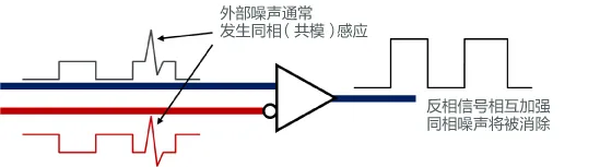
Regarding external noise
In addition, paired signal lines are adjacent, so the magnetic fields generated by signal currents cancel out each other, which has the advantage of not easily radiating noise to the outside.
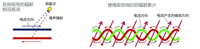
Regarding noise radiation
03
Noise issues in on-board Ethernet
Although differential transmission lines are considered less prone to noise generation, they can generate common mode currents due to various factors, leading to noise problems (as shown in the figure below).
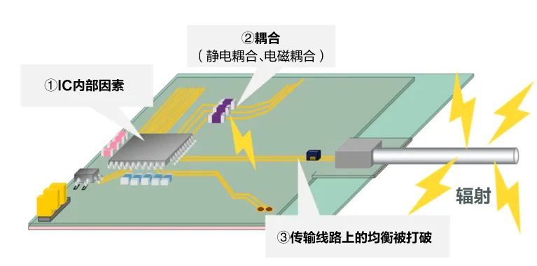
Common mode current generated due to various factors
04
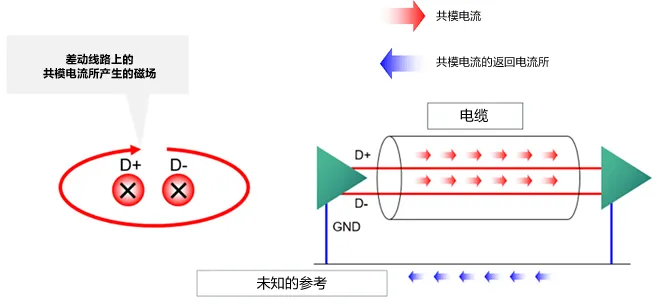
The Factors Causing Common Mode Noise
The characteristic of differential transmission lines was originally that they do not generate common mode noise, but if there is a signal bias (time deviation) or amplitude deviation between the two lines, the signal balance of the two lines will be disrupted, resulting in common mode noise (as shown in the figure below).
Normal differential signals and situations with skewness and amplitude deviation
Differential mode: The normal differential signal is different from the situation when there is deviation or amplitude deviation
Common mode: normal differential signals and situations with skewness and amplitude deviation
05
Noise reduction measures for on-board Ethernet
There are differences between cables used for Ethernet and cables used for HDMI, USB, etc.
Unlike paired signal lines, cables such as HDMI or USB are equipped with GND lines, so even if common mode currents are generated, they will return through the GND lines, causing the magnetic fields generated by common mode currents to cancel out each other and prevent radiation. On the contrary, Ethernet is not configured with GND lines, so common mode current is returned through stray capacitance to ground, making it prone to radiation.

Cable for HDMI, USB, etc
GND wires have been added to the cable, thus eliminating some of the magnetic field generated by common mode currents. So, the radiation generated by common mode current is reduced.
Ethernet cables
There is no GND cable in the Ethernet cable, so the magnetic field generated by common mode current cannot be eliminated. The increase in radiation caused by common mode current requires noise reduction through components.
Common mode choke (CMCC) is more effective in differential transmission noise reduction measures such as in car Ethernet. A common mode choke wraps two wires in opposite directions around the same coil core. For differential mode current, the magnetic flux generated by the two wires cancels out each other, thus not affecting the differential current. However, for common mode current, the magnetic flux generated by the two wires strengthens each other, so it can be used as an inductor. Therefore, the common mode choke can effectively reduce common mode noise without affecting the differential signal.
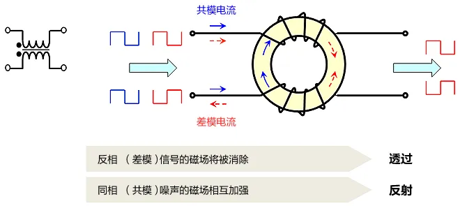
Ethernet cables can selectively eliminate only common mode noise.
06
Notes on CMCC for in car Ethernet
In terms of in car Ethernet, the balance of CMCC is also important. If there is a deviation in the length and winding method of the two lines that make up CMCC, the current balance will be disrupted, and the mode will switch, which may result in common mode noise. Therefore, two lines with balanced design should be selected for CMCC.
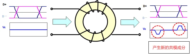
Notes on CMCC for in car Ethernet
If there is a deviation in the length of the CMCC line between two coils, new common mode noise may be generated due to mode switching. Components with fewer mode transitions should be selected.
As the most suitable CMCC for 1000Base-T1 noise reduction, DLW32MH101XT2 has been developed as a product. This Murata product has an impedance value suitable for 1000Base-T1 and adopts a balanced design that is not prone to mode switching.

Recommended by Murata:
Click on the image to learn more

DLW32MH101XT2
DLW32MH101XT2 has the following three advantages:
It can effectively reduce the noise emitted by the internal network signal lines of the car.
Complies with the car Ethernet standard 1000Base-T1.
Can handle the working temperature range for automotive use (-40~125 ° C).
The transmission characteristics of DLW32MH101XT2 are shown in the following figure:
The transmission characteristics of DLW32MH101XT2 include:
Sdd21 (Differential Mode Transmission Characteristics)
Scc21 (Common Mode Transmission Characteristics)
Sdd11 (Differential Mode Reflection Characteristics)
Ssd12 (Mode Conversion Characteristics)
07
Conducted emission countermeasures
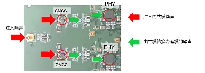
Murata conducted conducted conducted emission measurements using a 1000Base-T1 EMC evaluation board (150 Ω method).
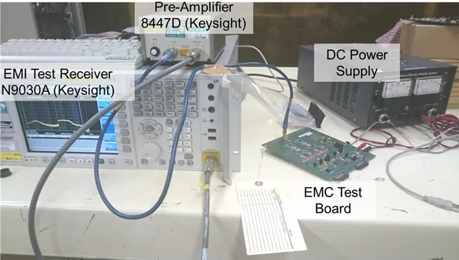
Conducted emission measurement
The measurement conditions for conducted emissions are shown in the table below:
|
frequency |
150k – 1600MHz |
|
RBW |
9kHz (150k-30MHz) 120kHz (30-1600MHz) |
|
Dwell Time |
5ms/Hz |
|
Step Size |
3.6kHz (150k-30MHz) 48kHz (30-1600MHz) |
|
EUT |
1000Base-T1 EMC Test Board |
|
EMI Test Receiver |
N9030A(Keysight) |
|
Pre-Amplifier |
8447D(Keysight) |
|
DC Power Supply |
GP035-5(Takasago) |
Extract common mode noise from the signal line of the 1000Base-T1 EMC evaluation board and measure it using an EMI receiver. This time, a noise comparison was conducted by replacing the CMCC.
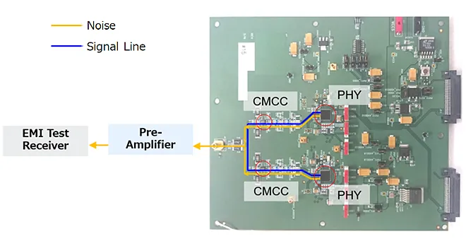
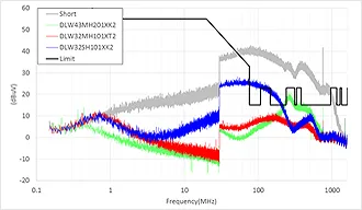
Comparison of noise reduction effects of different CMCC
The CMCC used for evaluation used product DLW32MH101XT2 for 1000Base-T1, compared to product DLW43MH201XK2 for 100Base-T1, and product DLW32SH101XK2 for CAN. (Note: DLW32SH101XK2 has been discontinued in the CMCC used to reduce conducted emissions).
Compare the transmission characteristics of the components, including:
Sdd21 (Differential Mode Transmission Characteristics)
Scc21 (Common Mode Transmission Characteristics)
Sdd11 (Differential Mode Reflection Characteristics)
Ssd12 (Mode Conversion Characteristics)
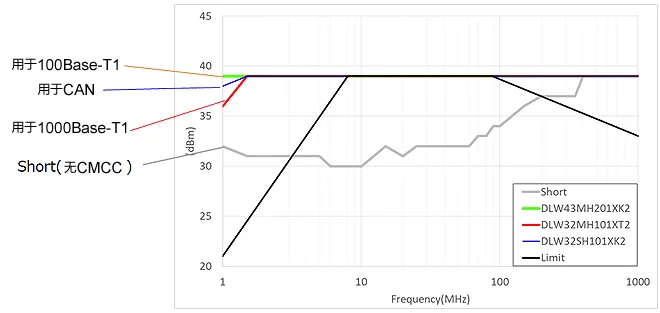
The conducted emission measurement results show that the noise suppression effect of the product DLW32MH101XT2 used for 1000Base-T1 is the most significant and meets the limit requirements. However, DLW43MH201XK2 and DLW32SH101XK2 failed to suppress noise before meeting the limit requirements.
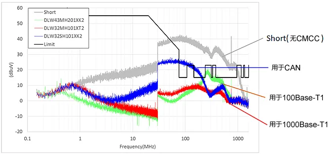
Conducted emission measurement results
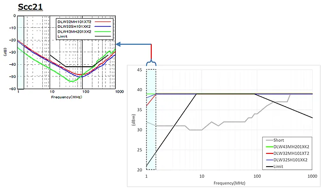
The reason why the noise suppression effect varies with CMCC may be influenced by the mode conversion characteristic Ssd12 of CMCC. When the Ssd12 value is high, the proportion of input differential mode signal converted to common mode noise will increase, leading to an increase in noise level.

Noise generation mechanism
The degree to which Scc21 suppresses common mode noise in the low frequency range and the degree to which the mode conversion characteristics of Ssd12 reduce common mode conversion in the high frequency range may affect the results of conducted emission measurements.
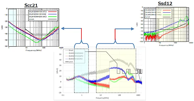
Key points of noise reduction
By evaluating CMCC, Murata learned about the considerations for designing evaluation boards during the evaluation process.
After attaching the same CMCC sample used for 1000Base-T1 to an evaluation board under the same conditions, the results showed that the noise levels of the two were different, with one evaluation board becoming NG.
Even for the same CMCC sample, NG may occur due to the evaluation of the board status
。
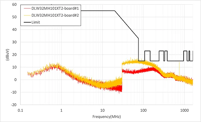
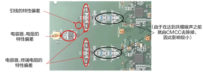
Notes on Evaluation Board Design
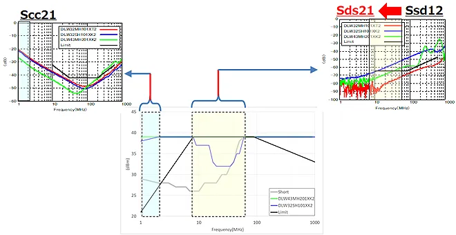
By analyzing the transmission line characteristics of the evaluation board, it was found that the mode conversion characteristics of the CMCC output end are different, and the value of evaluation board # 2 is higher (as shown in the above figure).
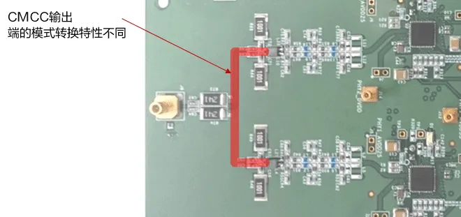
The part where pattern switching occurs
The reason why the level of conducted noise varies depending on the evaluation board is that the differential mode signal after CMCC is converted into common mode noise on the evaluation board.
The factors that trigger mode switching may include the resistance of the CMCC output terminal, capacitors, and circuit board leads, which lead to the occurrence of imbalance due to their characteristic deviations.
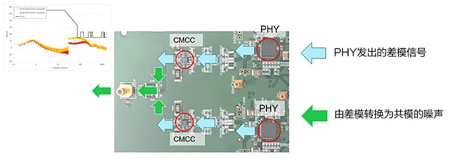
Mechanism of pattern transition
Therefore, for parts outside of CMCC, attention should also be paid to maintaining a balanced characteristic of each line.
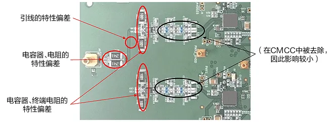
Possible factors that may trigger pattern switching
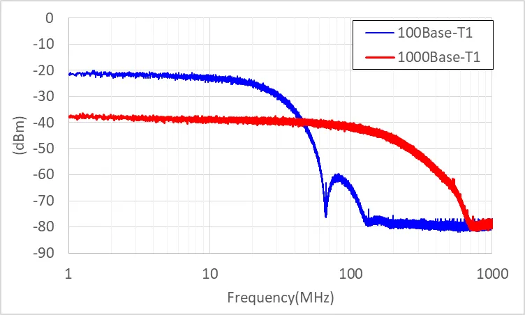
As a comparative verification, we also measured the conducted emission of 100Base-T1.
After conducting the same conducted emission measurements on 100Base-T1, it was found that the DLW32SH101XK2 used for CAN exceeded the limit, while the product DLW43MH201XK2 used for 100Base-T1 was able to effectively suppress noise and meet the limit requirements.

Conducted emissions of 100Base-T1 and 1000Base-T1
Key points:
The difference between 100Base-T1 and 1000Base-T1:
The frequency components of the differential mode signals of 100Base-T1 and 1000Base-T1 are different (as shown in the figure below), so the required mode conversion characteristics are also different. Therefore, CMCC designed according to their respective standards should be selected.
Differential signal waveform spectrum
08
DPI Test Countermeasures
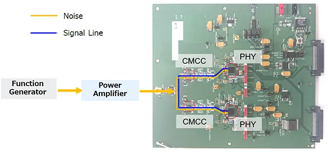
Murata conducted DPI (Direct Power Injection) tests using the same 1000Base-T1 EMC evaluation board as conducted emissions.
DPI Test Countermeasures
The measurement conditions for the DPI test are shown in the table below:
|
frequency |
1 - 1000MHz |
|
Power(MAX) |
39dBm |
|
Power Step |
0.5dB |
|
EUT |
1000Base-T1 EMC Test Board |
|
DC Power Supply |
GP035-5(Takasago) |
|
Signal Generator |
SML02(Rohde&Schwarz) |
|
Power Amplifier |
BSA1040-100 (1-400MHz) BLWA4010-100 (400-1000MHz) |
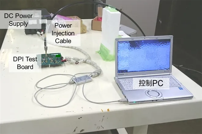
Injecting common mode noise into the signal line of the 1000Base-T1 EMC evaluation board from the outside confirmed whether a communication error occurred in the control PC.
DPI Test Countermeasures
Similar to conducted emission, this experiment evaluated CMCC for 1000Base-T1, namely DLW32MH101XT2, DLW43MH201XK2 for 100Base-T1, and DLW32SH101XK2 for CAN.
Compare the transmission characteristics of the components, including:
Sdd21 (Differential Mode Transmission Characteristics)
Scc21 (Common Mode Transmission Characteristics)
Sdd11 (Differential Mode Reflection Characteristics)
Ssd12 (Mode Conversion Characteristics)
DPI test results for 1000Base-T1:
In the low frequency range below 2MHz, although the level may vary due to different CMCC, there is no difference in other performance, meeting all limits.

DPI test results for 1000Base-T1
The differences caused by CMCC in the frequency band below 2MHz may depend on the Scc21 factor. The differences caused by the mode switching characteristics did not affect the DPI test.
DPI test results for 1000Base-T1
09
Key points of anti-interference (DPI) test countermeasures
After 1000Base-T1, the DPI test results conducted at 100Base-T1 (as shown in the figure below) showed that the CMCC used for 100Base-T1 met the limit requirements. However, when using CMCC used for CAN, not only did it perform worse in the low-frequency band below 1MHz than the CMCC used for 100Base-T1, but it also fell below the limit in the range of 8-60MHz, resulting in NG.
DPI test results for 100Base-T1
The difference in frequency bands below 2MHz may depend on the Scc21 factor. In addition, the differences in the 8-60MHz frequency band may depend on the mode conversion characteristics.
DPI test results for 100Base-T1
At 100Base-T1, the mode conversion characteristics of CMCC have an impact on the experimental results, which may be due to the conversion of common mode noise injected externally to differential mode noise, causing distortion of the signal waveform and leading to communication errors.
Noise intrusion mechanism
Similar to conducted emission, mode switching caused by uneven design on the evaluation board can also have an impact, except for CMCC. Therefore, attention should be paid when designing the evaluation board. An example of factors that may trigger pattern switching is shown in the following figure:
Notes on Evaluation Board Design
ten
Summary
The 1000Base-T1 in car Ethernet standard requires high performance for noise cancelling CMCC, and mode conversion characteristics are particularly important.
When evaluating conducted emissions, it is necessary to prepare a CMCC that meets the required value of 1000Base-T1 and has mode conversion characteristics to achieve noise suppression. The CMCC used for CAN or 100Base-T1 cannot meet the limit requirements.
Even when using CMCC for 1000Base-T1, it is possible that the performance of mode conversion characteristics may decrease and noise may increase due to deviations in the design of the circuit board or the components to be installed. Therefore, attention should be paid during design.
The immunity test, i.e. DPI test, has lower requirements for the performance of CMCC compared to conducted emission test. However, since the noise resistance varies by PHY, it is recommended to choose CMCC with lower mode conversion characteristics.
The relevant product information mentioned in the article is as follows (click on the product name to enter the product page):
|
Corresponding to I/F |
1000Base-T1 |
100Base-T1 |
|
model |
DLW32MH101XT2 |
DLW43MH201XK2 |
|
size |
3.2×2.5mm |
4.5×3.2mm |
|
Common mode inductance |
100μH typ |
200μH typ |
|
Rated current |
100mA |
110mA |
Note: The DLW32SH101XK2 used in testing has been discontinued from production.

Tel:86-755-28100016
Email:sales.cn@uxingroup.com
Address:7th floor, block B, building 9, Baoneng Science Park, Qingxiang Road, Longhua District, Shenzhen City, Guangdong Province, China
